


The material in each layer, and what it changes on the press
Surface, core and end face, in the order they matter on the press. Each material choice is tied to a measurable result.
Epoxy resin instead of polyurethane
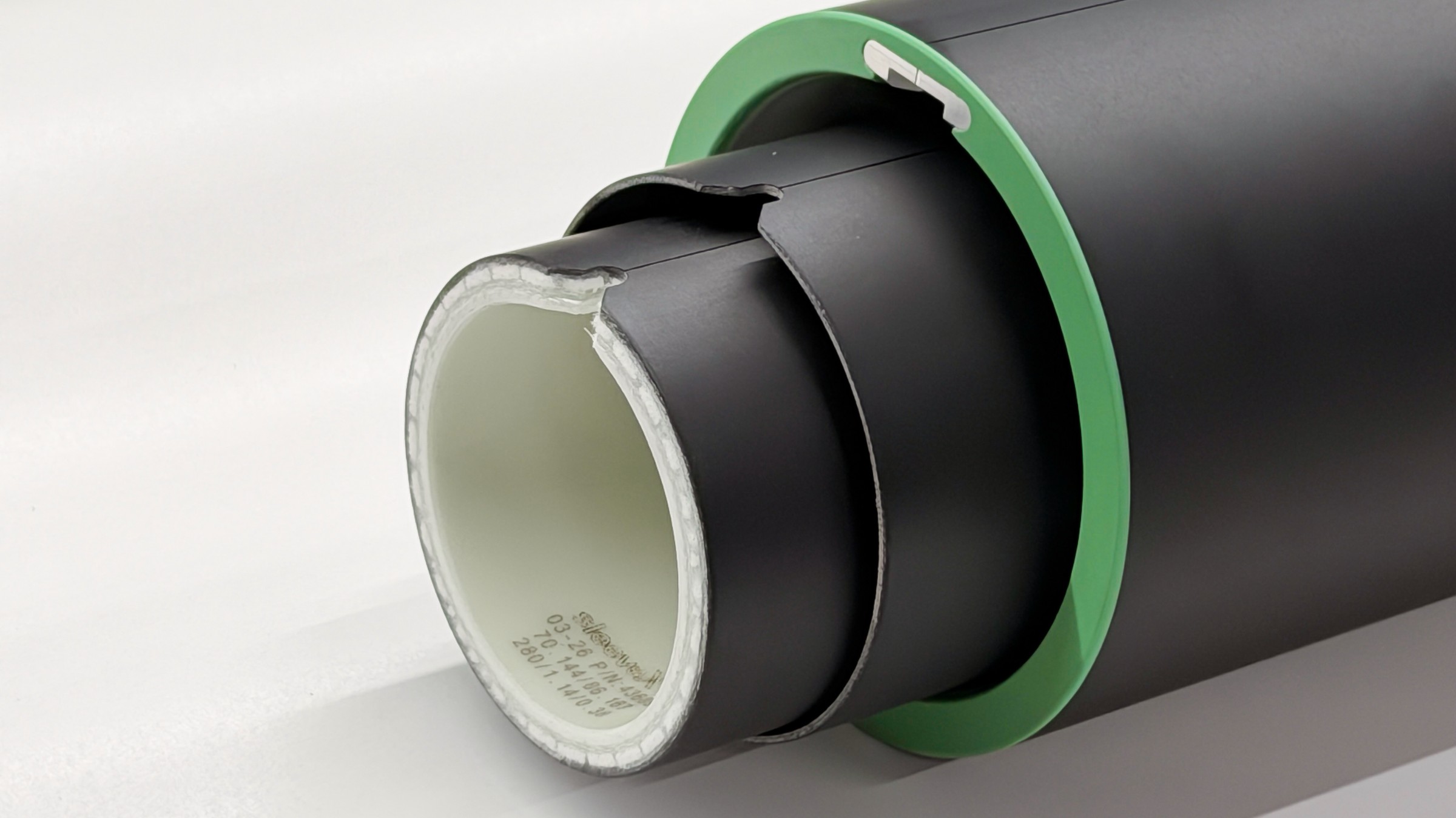
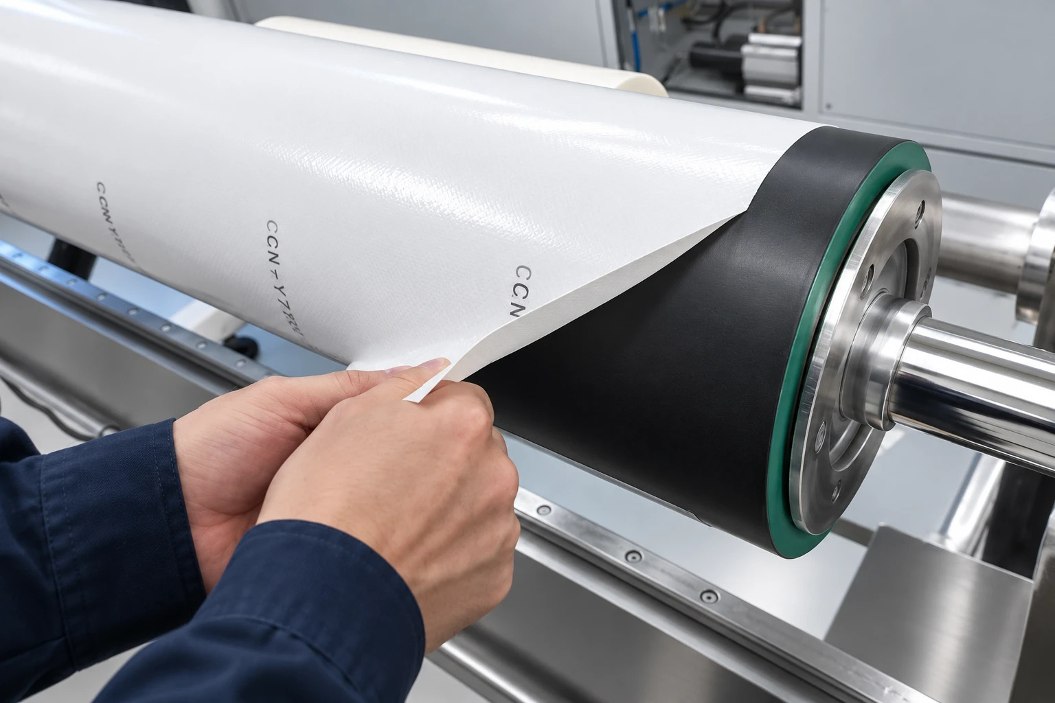
Most of what happens to a sleeve happens on its surface: plate mounting, the peel force of stripping tape, and solvent cleaning. sleeveX™ uses a dense epoxy resin system, Shore D82 and D90 on the ultra-thin X-MUT — scratch-resistant, tolerant of cleaning solvents and available in an antistatic version.
- Shore D82 epoxy surface (D90 on X-MUT)
- Tolerates cleaning solvents
- Scratch-resistant, antistatic version available
Mounting tape: brands, grades and tack levels
Mounting and stripping plate tape is what this surface does most often.
- Tested across the major brands, grades and tack levels
- Less residue on removal
- Consistent behaviour across tape changes
Aramid honeycomb instead of PU foam
The support layer of a conventional sleeve is foamed polyurethane. It is light, but it absorbs water, compresses under load and expands with temperature. The X-MLW lightweight model uses an aerospace-grade aramid honeycomb instead: a bonded cell structure with very low density, water absorption below 0.5% and thermal expansion of 2–5 ppm/°C. The thinner models carry the same load in glass-fibre and composite structures.
A support layer that carries the load in a bonded composite rather than a foam, behind an end face moulded in one piece
The six layers, outside in
Six layers on the X-MLW lightweight model, from the printing surface inward. The thinner models use the structures listed on the Products page.
- Hard polyurethane surface — pushed up by the swelling core, lifts off the substrate
- PU foam support — swells with moisture and pushes the surface out; compresses under load
- Unsealed end face — solvent wicks in and the layers delaminate
The six-layer build applies to the X-MLW lightweight model (10–100 mm wall). Thinner models use the structures listed on the Products page.
Compare all four modelsSilentShield™ and full end sealing
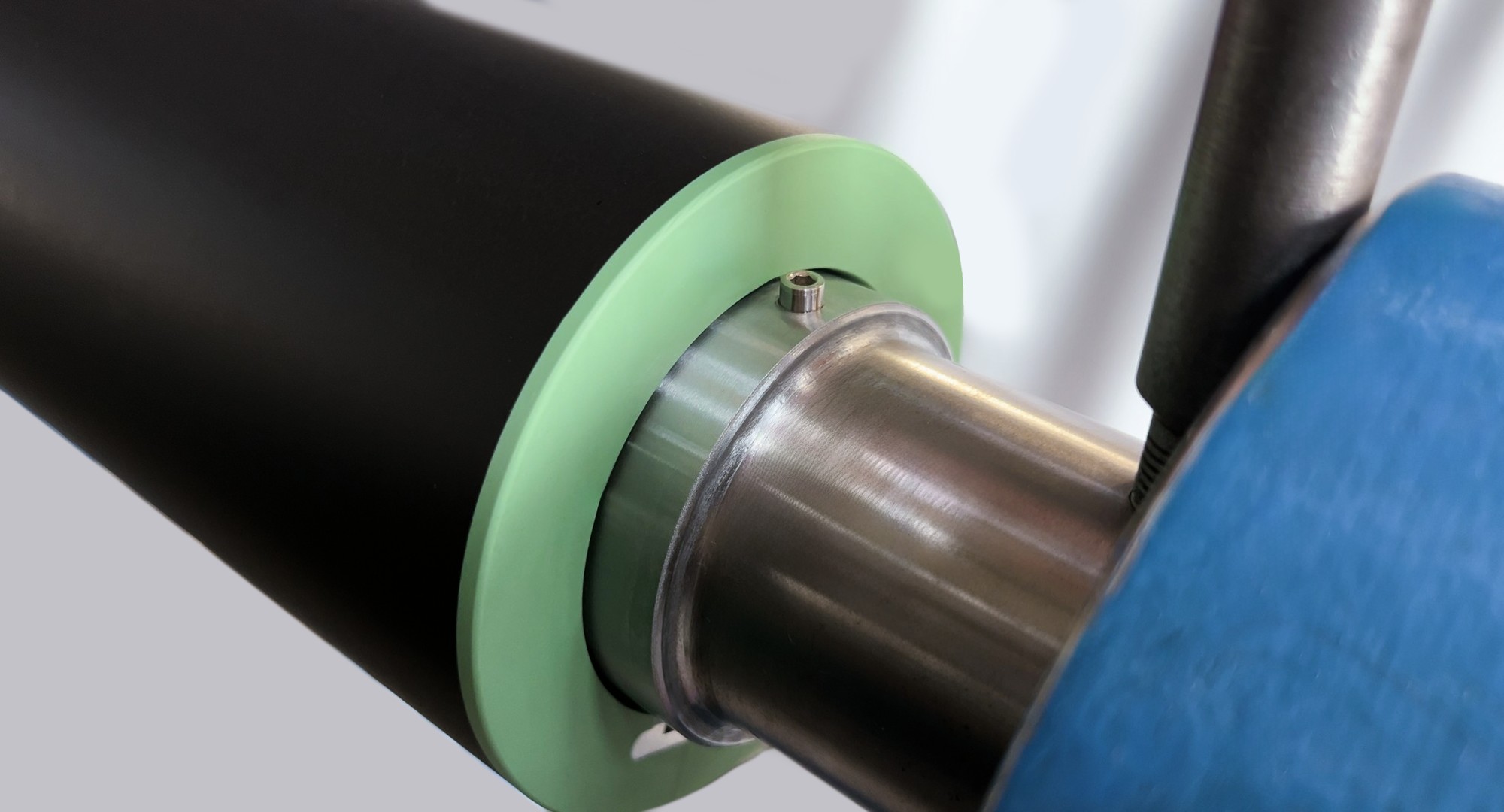
The end face is where sleeves get damaged and where solvent gets in. Both problems are handled in the same moulded part.
Impact-absorbing end face
A high-toughness polymer moulded as one piece with the sleeve body. It absorbs the energy of a knock during loading, which protects the end against cracking and delamination.
Sealed across the whole end
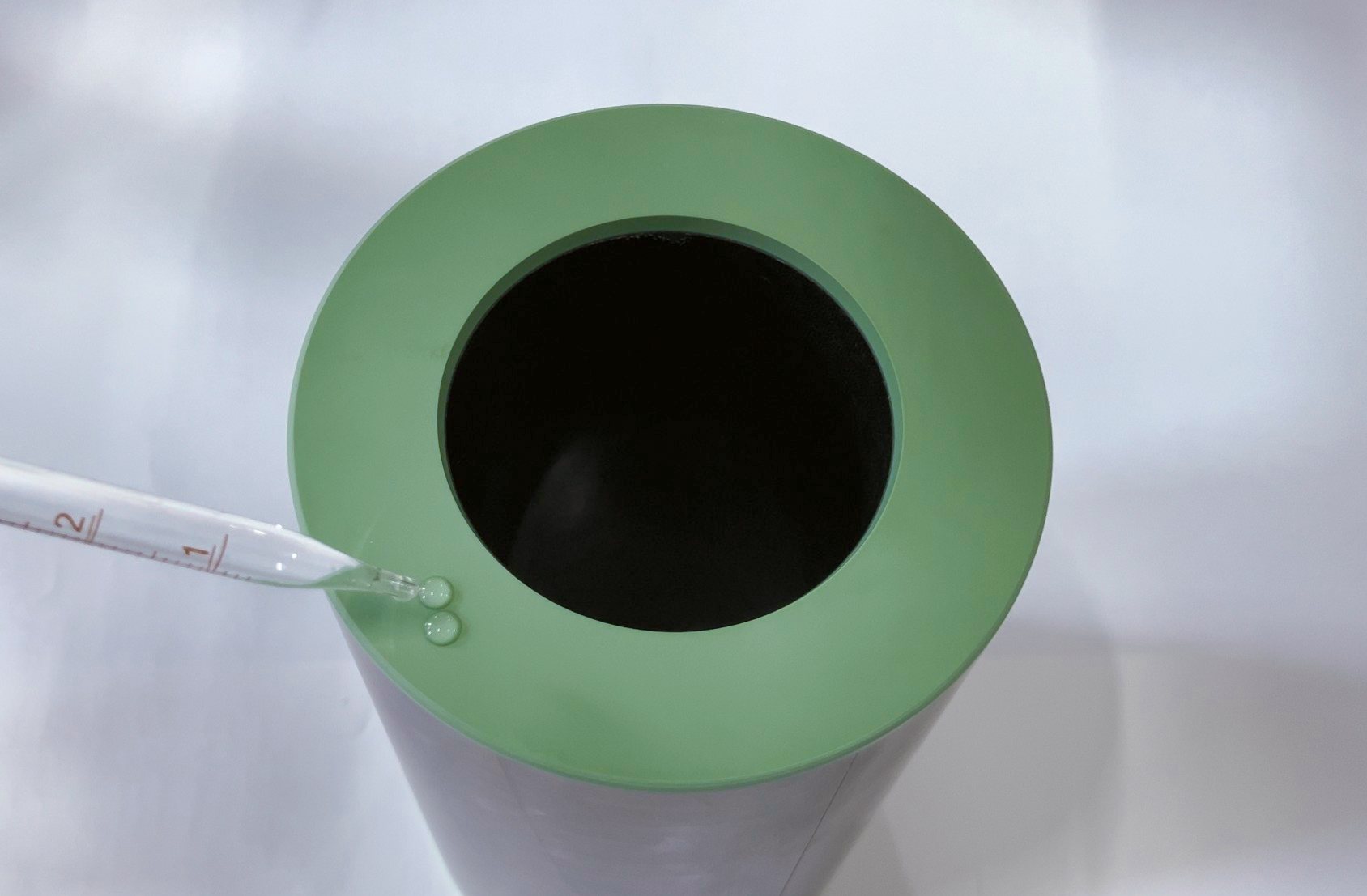
A continuous physical barrier blocks the capillary path that ink and cleaning solvent use to enter the structure. Liquid sits on the surface instead of soaking in.
The liner that decides whether the sleeve slips
The liner is wound in-house on equipment we developed ourselves, in a temperature- and humidity-controlled shop. Three process controls give it a consistent grip, batch after batch.
- 1
Constant tension control
A closed-loop system holds winding tension steady, which reduces local stress concentrations in the liner and keeps grip even around the circumference.
- 2
Fibre path modelling
The lay-up path is optimised by algorithm. This is what gives the liner its memory effect, so grip on the mandrel stays consistent.
- 3
Automatic resin interface
Resin wetting is metered to balance interlayer bonding against damping, so the liner stays bonded and still damps vibration at speed.
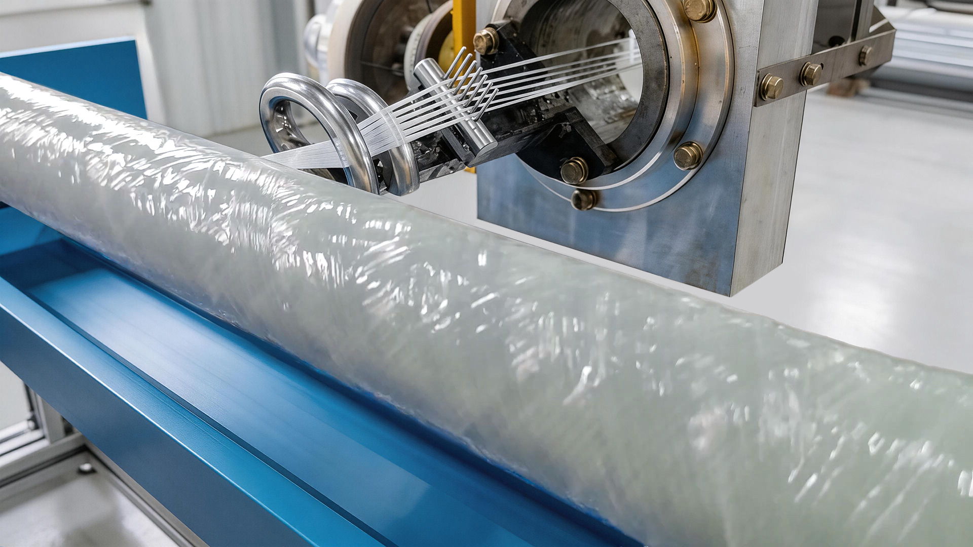
Wound in-house, in a controlled shop
The liner is produced on winding equipment Auclean developed in-house in a temperature- and humidity-controlled workshop. Winding in-house under controlled conditions is what keeps dimensions consistent between sleeves in one batch, and between batches of the same size.
In our tests the liner does not slip at 650 m/min or through rapid acceleration and deceleration, and mounts and dismounts with appropriate tightness.
Four properties, three core materials
The layer under the surface is what holds the diameter. These are the published ranges for the three fills this industry builds sleeves around, for comparison against the datasheet of any sleeve currently in service.
Ranges as published in our product documentation. We do not convert them into a single figure.
Thermal expansionppm/°C
lower is betterRegistration drift as the press warms up
- sleeveX™ honeycomb2–5
- PU foam50–150
- Felt20–40
Densitykg/m³
lower is betterHandling weight at every changeover
- sleeveX™ honeycomb20–80
- PU foam30–120
- Felt60–650
Water absorption%
lower is betterSwelling in humid plants or after solvent cleaning
- sleeveX™ honeycomb< 0.5
- PU foam1–5
- Felt1–3
Flexural strengthMPa
higher is betterGoing soft under years of mounting pressure
- sleeveX™ honeycomb20–40
- PU foam0.5–1.5
- Felt8–16
Every sleeve is measured before it leaves
Four numbers a press OEM or a technical buyer can re-check at incoming inspection
Print size and registration accuracy
Even impression, less local colour variation
Dot accuracy, less ghosting
Smooth running at high speed
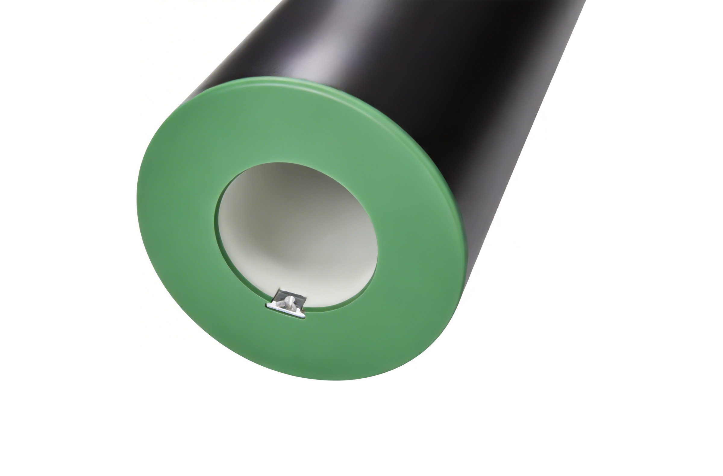
Locating notch
Metal, machined on our own equipment to the international standard size. Compatible with a range of press brands.
Antistatic option
Through-body antistatic build on any model, resistance to ground below 1×10⁶ Ω, for film printing.
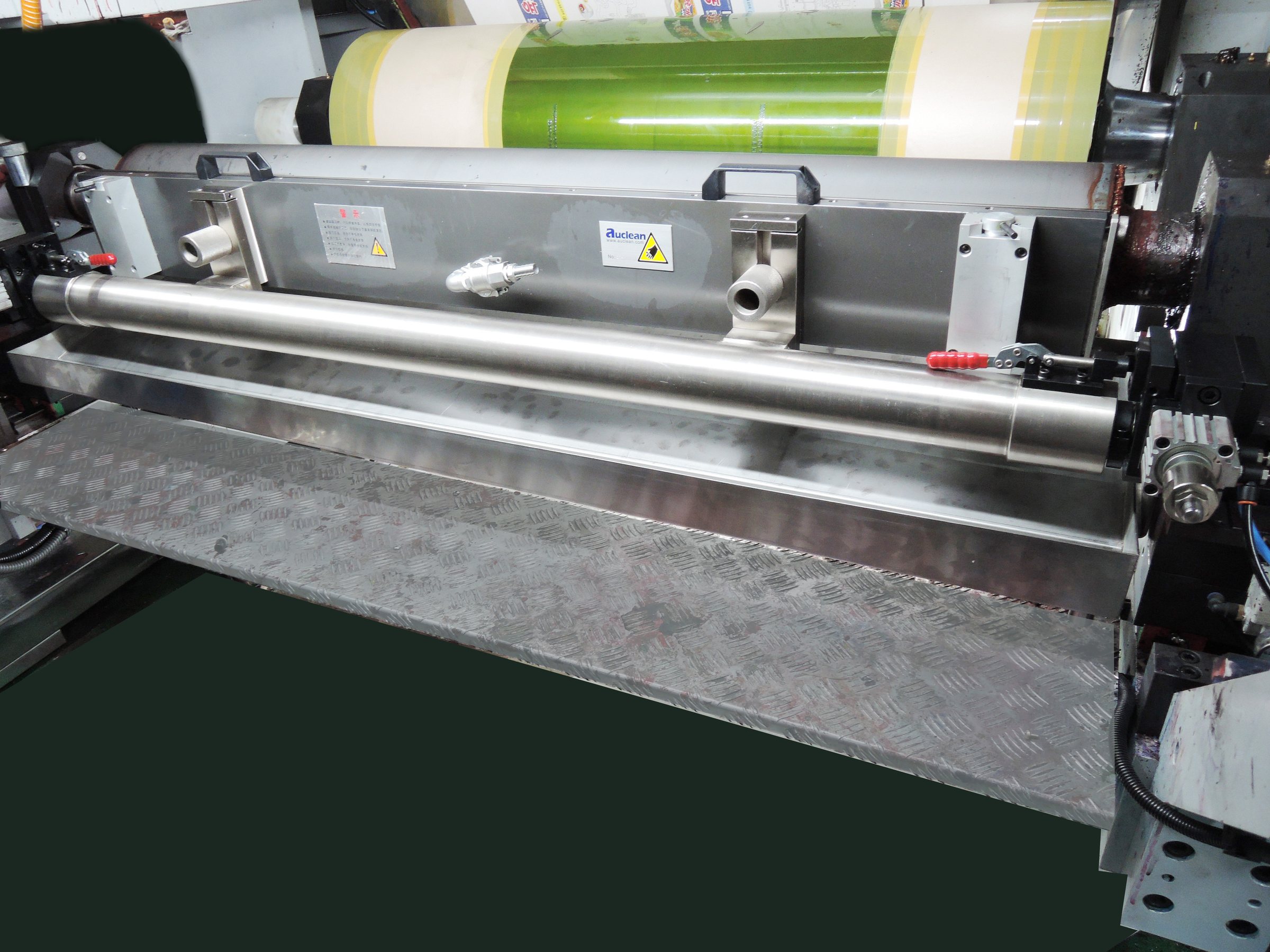
Eight years on one press
Early sleeveX™ samples have been running on a customer's press for eight years. The outer diameter is essentially unchanged. This is service data from one press over that period, not a laboratory result.
Technical datasheet for a given model and size
Tell us the model and dimensions and an engineer will reply with the relevant figures.